
sales06@switek.biz

+86 186 5927 5869

Subscript to Us
sales06@switek.biz
+86 186 5927 5869
Subscript to Us
Keywords:Panasonic A6 Servo Installation Instruction, Panasonic A6 Driver, Panasonic A6 Series Servo Motor Manual
The torque control is performed according to the torque command specified in the form of analog voltage. For controlling the torque, the speed limit input is required in addition to the torque command to maintain the motor speed within the speed limit.
With the A5 series, 3 torque control modes are available, each requires different torque command and speed limit as shown in the table below.
• Pr3.17 (Selection of torque command)
| Parameter | Title | Torque command input | Velocity limit input |
|---|---|---|---|
| 0 | Selection of torque command 1 | Analog input 1*1 (Al1, 16-bit resolution) | Parameter value (Pr3.21) |
| 1 | Selection of torque command 2 | Analog input 2 (Al2, 12-bit resolution) | Analog input 1 (Al1, 16-bit resolution) |
| 2 | Selection of torque command 3 | Analog input 1 *1 (Al1, 16-bit resolution) | Parameter value (Pr3.21, Pr3.22) |
*1 For Pr0.01 Control mode setup = 5 (velocity/torque control), the torque command input is the analog input 2 (Al2, 12-bit resolution).
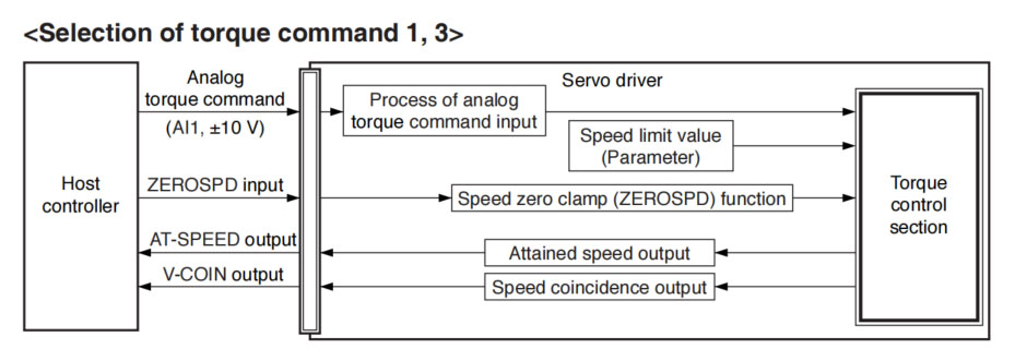
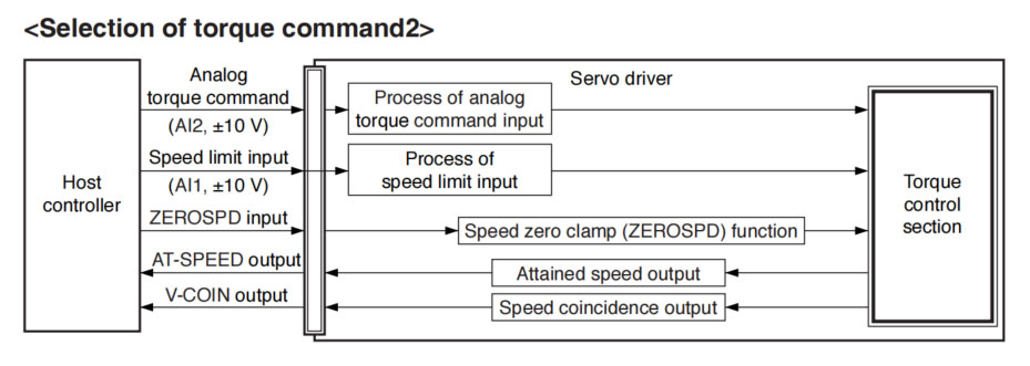
This process converts the analog torque command input (voltage) to the equivalent digital torque command having the same effect. You can set the filter or adjust the offset to eliminate noise.
• Relevant parameters <Selection of torque command 1, 3>
| Parameter No. | Title | Range | Unit | Function |
|---|---|---|---|---|
| Pr3.18 | Torque command direction selection | 0 to 1 | — | Select the direction positive/negative direction of torque command. |
| Pr3.19 | Torque command | 10 to 100 | 0.1 V/100 % | Based on the voltage (V) applied to the analog torque command (TRQ R), set up the conversion gain to torque command (%). |
| Pr3.20 | Input reversal of torque command | 0 to 1 | — | Set up the polarity of the voltage applied to the analog torque command (TRQR). |
| Pr4.22 | Analog input 1 (Al1) offset setup | -5578 to 5578 | 0.359 mV | Set up the offset correction value applied to the voltage fed to the analog input 1. |
| Pr4.23 | Analog input 1 (Al1) filter | 0 to 6400 | 0.01 ms | Set up the time constant of 1st delay filter that determines the lag time behind the voltage applied to the analog input 1. |
• Relevant parameters <Selection of torque command 2>
| Parameter No. | Title | Range | Unit | Function |
|---|---|---|---|---|
| Pr3.18 | Torque command direction selection | 0 to 1 | — | Select the direction positive/negative direction of torque command. |
| Pr3.19 | Input gain of torque command | 10 to 100 | 0.1 V/100 % | Based on the voltage (V) applied to the analog torque command (TRQ R), set up the vonversion gain to torque command (%). |
| Pr3.20 | Input reversal of torque command | 0 to 1 | — | Set up the polarity of the voltage applied to the analog torque command (TRQR). |
| Pr4.25 | Analog input 2 (Al2) offset setup | -342 to 342 | 5.86 mV | Set up the offset correction value applied to the voltage fed to the analog input 2. |
| Pr4.26 | Analog input 2 (Al2) filter | 0 to 6400 | 0.01 ms | Set up the time constant of 1st delay filter that determines the lag time behind the voltage applied to the analog input 2. |
The speed limit is one of protective functions used during torque control. This function regulates the motor speed so that it does not exceed the speed limit while the torque is controlled.
• Relevant parameters <Selection of torque command 1, 3>
| Parameter No. | Title | Range | Unit | Function |
|---|---|---|---|---|
| Pr3.21 | Speed limit value 1 | 0 to 20000 | r/min | Set the speed limit used for torque controlling. |
| Pr3.22 | Speed limit value 2 | 0 to 20000 | r/min | |
| Pr3.15 | Speed zero-clamp function selection | 0 to 3 | — | You can set up the function of the speed zero clamp input. |
• Relevant parameters <Selection of torque command 2>
| Parameter No. | Title | Range | Unit | Function |
|---|---|---|---|---|
| Pr3.02 | Input gain of speed command | 10 to 2000 | (r/min) /V | Based on the voltage applied to the analog speed command (SPR), set up the conversion gain to motor command speed. |
| Pr4.22 | Analog input 1 (Al 1) offset setup | -5578 to 5578 | 0.359 mV | Set up the offset correction value applied to the voltage fed to the analog input 1. |
| Pr4.23 | Analog input 1 (Al1) filter | 0 to 6400 | 0.01 ms | Set up the time constant of 1st delay filter that determines the lag time behind the voltage applied to the analog input 1. |
| Pr3.15 | Speed zero-clamp function selection | 0 to 3 | — | You can set up the function of the speed zero clamp input. |

HD170LDY -- HaiDa Hybrid Injection Molding Machine
| No. | Name | Value |
|---|---|---|
| 1 | Clamping Force | 1700 kN |
| 2 | Shot Weight | 147 g |
| 3 | Shot Speed | 200 mm/s |
| 4 | Screw Diameter | 36 mm |
| 5 | Opening Stroke | 440 mm |
| 6 | Space Between Tie Bars | 470 x 470 mm |
| 7 | Mold Thickness (Min) | 200 mm |
| 8 | Mold Thickness (Max) | 520 mm |
| 9 | Pumper Motor | 56 kW |
| 10 | Heating Capacity | 11 kW |

The SWITEK side entry petri dish packing system is a custom made automation system for the stable production of laboratory consumable plastic petri dish with the picking robot, the petri dish assembly, stacking, packing unit etc. integrated as auniformed system for the efficient and stable production of the petri dish. The system can be custome made for a petri dish mold layout design of 2+2, 4+4, 6+6, 8+8 etc.


Mold Layout Deisgn

Sleeve Size for Package with Vacuum Request

Sleeve Size for Package without Vacuum Request

Sleeve (With Mark) Size for Package with Vacuum Request

Sleeve (With Mark) Size for Package without Vacuum Request
I think you'll have an overall understanding about the SWITEK top/side entry petri dish packing system. If you still have any other question about it or need any help in your petri dish production project, please feel free to contact SWITEK laboratory consumable plastic parts injection molding solutions team for more information.
HuangYanZheng©Copy Right


