
sales06@switek.biz

+86 186 5927 5869

Subscript to Us
sales06@switek.biz
+86 186 5927 5869
Subscript to Us
Keywords:Panasonic A6 Servo Motor, Panasonic A6 Servo Motor Driver, Panasonic A6 Servo Motor setting instruction
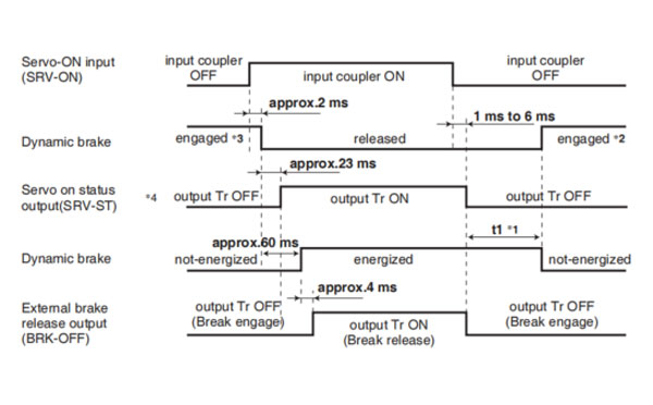
The timing chart shows the servo-on signal accept timing on power-up of a Panasonic A6 series AC servo motor from AC power-ON to command input.
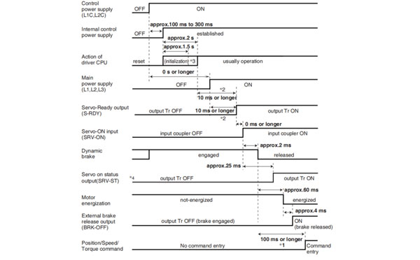
Caution → *1. In this term Servo-ON input (SRV-ON) turns ON as a hard ware, but operation command can not be received.
*2. S-RDY output will turn on when both conditionss are met, initialization of micro computer has been completed and the main power has been turned on.
*3. After internal control power supply, protective functions are active from approx. 1.5 sec after the start of initializing microcomputer. Please set the signals, especially for protective function, for example over-travel inhibit input (POT, NOT) or external scale input, so as to decide their logic unit this term.
The lapse time can be changed with Pr6.18 Wait time after power-up.
*4. Servo ON status output (SRV-ST) is a signal indicating that it has received the Servo-On input; please note that it is not an indication showing command input is possible.
Related page → •P.4-6 to P.4-85... "Details of parameter"
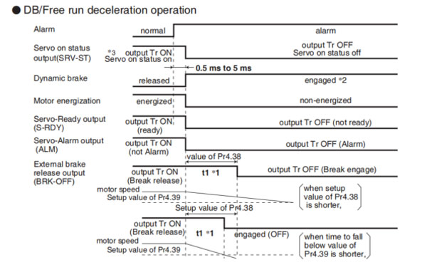
• DB/Free run deceleration operation
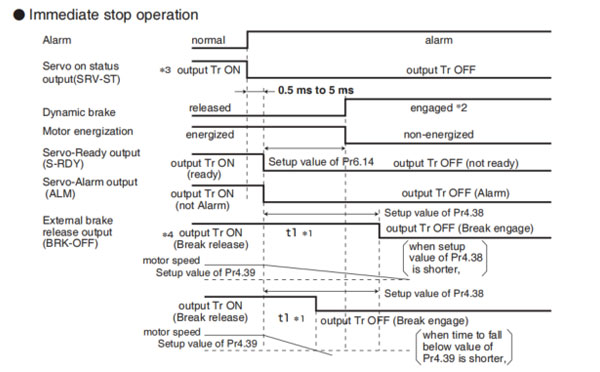
• Immediate stop operation
Caution → *1. t1 will be a shorter time of either the setup value of Pr4.38[Mechanical brake action at running setup] or elapsing time for the motor speed to fall below Pr4.39 [Brake release speed setup].
t1 will be 0 when the motor is in stall regardless of the setup pf Pr4.37.
*2. When an alarm is generated, the dynamic brake operates according to Pr5.10 Sequence at alarm.
*3. Servo ON status output (SRV-ST) is a signal indicating that it has received the Servo-On input; please note that it is not an indication showing command input is possible.
*4. The setting where Pr4.38 "Mechanical braking setting during operation" = Pr6.14 "Immediate stop time in case of alarm" is recommended.
When set to Pr4.38 ≤ Pr6.14, the brake will be operated after lapse of Pr4.38 time.
When set to Pr4.38 < Pr6.14, the brake will not operate even after lapse of Pr4.38 time, but will operate when transitioned to OFF state.
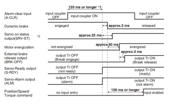
Caution → *1. The alarm clear input recognition time can be changed in Pr5.16 Alarm clear input setup.
*2. Servo ON status output (SRV-ST) is a signal indicating that it has received the Servo-On input; please note that it is not an indication showing command input is possible.
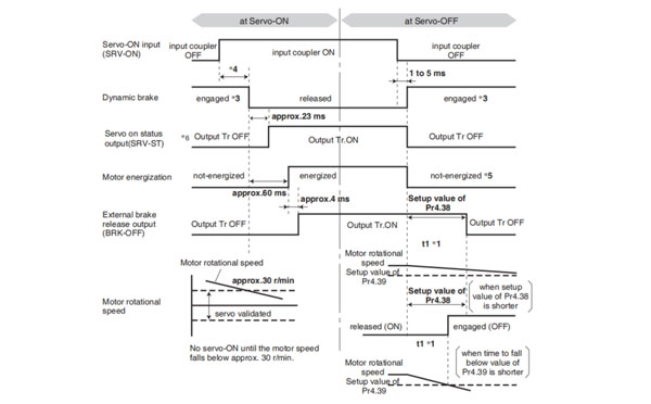
Remarks → To turn on/off the servo during normal operation, first stop the motor.
Caution → *1. t1 depends on the setup value of Pr4.37 Setup of mechanical brake action at stalling.
*2. The operation of dynamic brake during servo off depends on the setup value of Pr5.06 Sequence at servo off.
*3. Servo-ON will not be activated until the motor speed falls below approx.30 r/min.
*4. Servo ON status output (SRV-ST) is a signal indicating that it has received the Servo-On input; please note that it is not an indication showing command input is possible.
Related page → •P.4-47, 4-54 "Details of Parameter"
Remarks → Timing at emergency stop or trip. Do not repeat this sequence.
Caution → *1. t1 will be a shorter time of either the setup value of Pr4.38 "Mechanical brake action at running setup" or elapsing for the motor speed to fall below Pr4.39 "Brake release speed setup".
*2. Even though the SRV-ON signal is turned on again during the motor deceleration, Servo-ON will not be activated until the motor stops.
*3. For the action of dynamic brake at alarm occurrence, refer to an explanation of Pr5.06, "Sequence at Servo-OFF" as well.
*4. Servo-ON will not be activated until the motor speed falls below approx. 30r/min.
*5. For the motor energization during deceleration at Servo-OFF depends on the setup value of Pr.5.08, "Sequence at Servo-OFF".
*6. Servo ON status output (SRV-ST) is a signal indicating that it has received the Servo-On input; please not that it is not an indication showing command input is possible.
Related page → • P.2-47 "Dynamic brake"

HD210LDY -- HaiDa Hybrid Injection Molding Machine
| No. | Name | Value |
|---|---|---|
| 1 | Clamping Force | 2100 kN |
| 2 | Shot Weight | 257 g |
| 3 | Shot Speed | 200 mm/s |
| 4 | Screw Diameter | 40 mm |
| 5 | Opening Stroke | 500 mm |
| 6 | Space Between Tie Bars | 530 x 530 mm |
| 7 | Mold Thickness (Min) | 200 mm |
| 8 | Mold Thickness (Max) | 550 mm |
| 9 | Pumper Motor | 90 kW |
| 10 | Heating Capacity | 13 kW |

The SWITEK side entry petri dish packing system is a custom made automation system for the stable production of laboratory consumable plastic petri dish with the picking robot, the petri dish assembly, stacking, packing unit etc. integrated as auniformed system for the efficient and stable production of the petri dish. The system can be custome made for a petri dish mold layout design of 2+2, 4+4, 6+6, 8+8 etc.


Mold Layout Deisgn

Sleeve Size for Package with Vacuum Request

Sleeve Size for Package without Vacuum Request

Sleeve (With Mark) Size for Package with Vacuum Request

Sleeve (With Mark) Size for Package without Vacuum Request
I think you'll have an overall understanding about the SWITEK top/side entry petri dish packing system. If you still have any other question about it or need any help in your petri dish production project, please feel free to contact SWITEK laboratory consumable plastic parts injection molding solutions team for more information.
HuangYanZheng©Copy Right


