
sales06@switek.biz

+86 186 5927 5869

Subscript to Us
sales06@switek.biz
+86 186 5927 5869
Subscript to Us
Keywords:Panasonic A6 Servo Motor, Panasonic A6 Servo Motor Driver, Panasonic A6 Servo Motor setting instruction
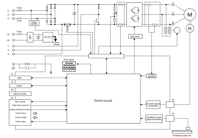
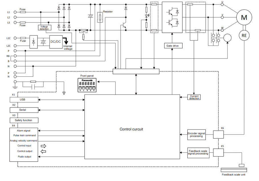
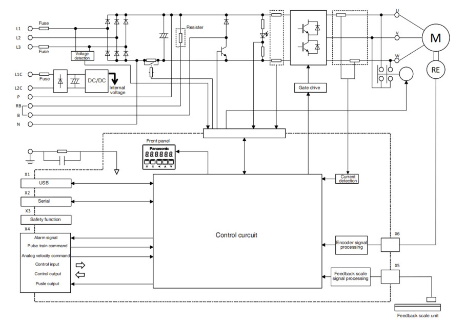
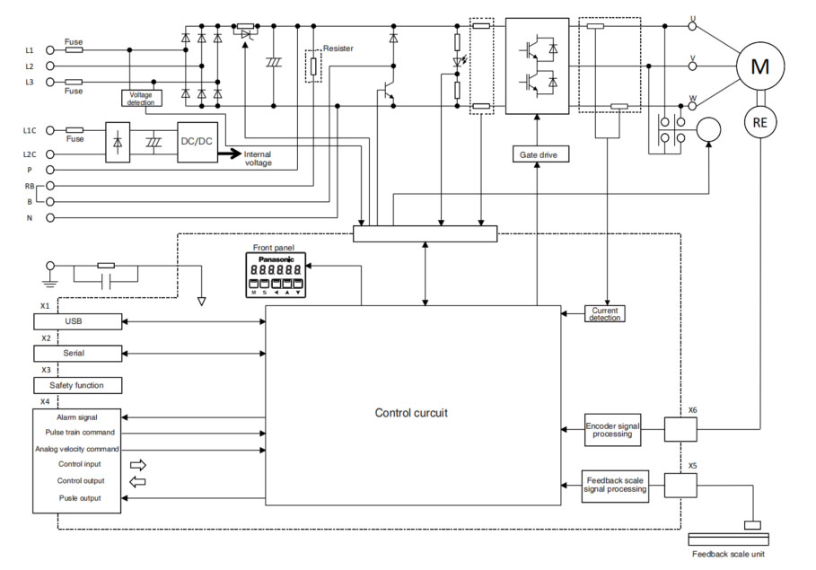
The specifications of the motors and driver will help you to choose the right one from the list of Panasonic A6 series of AC servo motor and drivers for your robotic arm and automation system. Here in this chapter you'll get the detailed list of the specifications and wiring diagram of the Panasonic A6 Series of AC servo motor and drivers.
| Basic Specifications | Input Power | 100V | Main circuit | Single phase, 100V to 120V +10%/-15% 50 Hz/60Hz | |
| Control circuit | |||||
| 200V | Main circuit | A to D-frame | Single/3-phase, 200V to 240V +10%/-15% 50Hz/60Hz | ||
| E to F-frame | 3-phase, 200V to 240V +10%/-15% 50Hz/60Hz | ||||
| Control circuit | A to F-frame | Single phase, 200V to 240V +10%/-15% 50Hz/60Hz | |||
| Withstand voltage | Primary to earth: withstand 1500 VAC, 1min, (sensed current 20mA) [100V/200V] | ||||
| Environment | temperature | Ambient temperature: 0°C to 55°C (free from freezing) Storage temperature: -20°C to 65°C (Max. temperature guarantee: 80°C to 72 hours free from condensation*1) | |||
| humidity | Both operating and storage: 20% to 85% RH or less (free from condensation*1) | ||||
| Altitude | Lower than 1000m | ||||
| Vibration | 5.88 m/s2 or less, 10Hz to 60Hz | ||||
| Control method | IGBT PWM Sinusoidal wave drive | ||||
| Encoder feedback | 23-bit (8388608 resolution) absolute encoder, 7-wire serial | ||||
| Feedback scale feedback | A/B phase, initialization signal defferential input. Manufactures that support serial communication scale (*2) Increment type Absolute type | ||||
| Parallel I/O connector | Control Signal | Input | Genral purpose 10 inputs The function of general-purpose input is selected by parameters. | ||
| Output | General purpose 6 outputs The function of general-purpose input is selected by parameters. | ||||
| Analog signal | Input | 3 inputs (16-bit A/D:1 input, 12-bit A/D:2 inputs) | |||
| Output | 2 outputs (Analog monitor: 2 outputs) Output from I/F connector pin 42, pin 43. | ||||
| Pulse signal | Input | 2 inputs (Photocoupler input, Line receiver input) Photocoupler input is compatible with both line driver I/F and open collector I/F. Line receiver input is compatible with line driver I/F. | |||
| Output | 4 outputs (Line driver: 3 output, open collector: 1 output) Feed out the encoder feedback pulse (A, B and Z-phase) or feedback scale pulse (EXA, EXB and EXZ-phase) in line driver. Z-phase and EXZ-phase pulse is also fed out in open collector. *When Block motion and full-closed control is valid, pulse signal can not be output. | ||||
| Communication function | USB | Connection with PC etc. | |||
| RS232 | 1:1 communication to a host. | ||||
| RS485 | 1:n communication to a host. | ||||
| Modbus-RTU | 1:1 communication to a host (RS232 communication) | ||||
| Safety function | Used for functional safety. | ||||
| Front panel | (1) 5keys (2) LED (6-digit) | ||||
| Regeneration | A, B-frame: No built-in regenerative resistor (external resistor only) C to F-frame: Built-in regenerative resistor (external resistor is also enabled.) | ||||
| Dynamic brake | A to F-frame: Built-in | ||||
| Control mode | Switching among the following 7 mode is enabled. (1) Position control (2) Velocity control (3) Torque control (4) Position/Velocity control (5) Position/Torque control (6) Velocity/Torque control (7) Full-closed control | ||||
| Function | Common | Auto Tuning | The load inertia is identified in real time by the driving state of the motor operating according to the command given by the controlling device and set up support software "PANATERM". The gain is set automatically in accordance with the rigidity setting. | ||
| Division of encoder feedback pulse | Set up of any value is enabled (encoder feedback pulses count is the max.). | ||||
| Protective function | Hard error | Over-voltage, under-voltage, over-speed, over-load, over-heat, over-current and encoder error etc. | |||
| Soft error | Excess position deviation, command pulse division error, EEPROM error etc. | ||||
| Traceability of alarm data | The alarm data history can be referred to. | ||||
| Infinite rotation absolute function | Available | ||||
| Deterioration diagnosis waring function | Available | ||||
| Position control | Control input | Deviation counter clear, command pulse input inhibition, command division/multiplication switching, vibraion suppression control switching, etc. | |||
| Control output | Positioning complete, etc. | ||||
| Pulse input | Max. command pulse frequency | Exclusive interface for Photocoupler and line driver: 500k pulse/s Exclusive interface for line receiver: 8 M Pulse/s | |||
| Input pulse signal format | Differential input. Selectable with parameter. ( (1) Positive and Negative direction, (2) A and B-phase, (3) Command and direction ) | ||||
| Electronic gear (Division/Multiplication of command pulse) | Process command pulse frequency x electronic gear ration (1 to 230/1 to 230) as position command input. Use electronic gear ration in the range 1/1000 times to 8000 times. | ||||
| Smoothing filter | Primary delay filter or FIR type filter is adaptable to the command input. | ||||
| Analog input | Torque limit command input | Individual torque limit for both positive and negative direction is enabled. | |||
| Torque feed forward input | Analog voltage can be used as torque feed forward input | ||||
| Vibration suppression control | Maximum of 3 may be used simultaneously | ||||
| Model-type damping filter | Maximum of 2 many be used simultaneously | ||||
| Two-degree-of-freedom control system | Available | ||||
| Load variation suppression function | Available | ||||
| Position compare output function | Available [Condition] Block operation valid setting Return to origin completed state in increment mode (when block operation origin return invalidation setting is set to invalid) | ||||
| External scale position information monitor function under semi-closed control | Available | ||||
| Block operation | Available *3 | ||||
| Internal Velocity control | Control input | Internal command velocity selection 1, Internal command velocity selection 2, Internal command velocity selection 3, speed zero clamp, etc. | |||
| Control output | Speed arrival, etc. | ||||
| Analog input | Velocity command input | Speed command input can be provided by means of analog voltage. Parameters are used for scale setting and command polarity. (6V/Rated rotational speed Default) | |||
| Torque limit command input | Torque limit can be applied to each direction respectively. | ||||
| Torque feed forward input | Analog voltage can be used as torque feed forward input. | ||||
| Internal velocity command | Switch the internal 8 speed is enabled by command input. | ||||
| Soft-start/down function | 0 to 10s/1000 r/min Setting is possible for acceleration and deceleration respectively. S shaped acceleration/decelaration is possible. | ||||
| Zero-speed clamp | Internal velocity command can be clamped to 0 with speed zero clamp input. | ||||
| Velocity command filter | Available | ||||
| Two-degree-of-freedom control system | Available | ||||
| Load variation suppression function | Unavailable | ||||
| External scale position information monitor function under semi-closed control | Unavailable | ||||
| Block operation | Available *3 | ||||

HD300KDY -- HaiDa Hybrid Injection Molding Machine
| No. | Name | Value |
|---|---|---|
| 1 | Clamping Force | 3000 kN |
| 2 | Shot Weight | 402 g |
| 3 | Shot Speed | 350 mm/s |
| 4 | Screw Diameter | 50 mm |
| 5 | Opening Stroke | 550 mm |
| 6 | Space Between Tie Bars | 590 x 590 mm |
| 7 | Mold Thickness (Min) | 220 mm |
| 8 | Mold Thickness (Max) | 600 mm |
| 9 | Pumper Motor | 147 kW |
| 10 | Heating Capacity | 21 kW |

The SWITEK side entry petri dish packing system is a custom made automation system for the stable production of laboratory consumable plastic petri dish with the picking robot, the petri dish assembly, stacking, packing unit etc. integrated as auniformed system for the efficient and stable production of the petri dish. The system can be custome made for a petri dish mold layout design of 2+2, 4+4, 6+6, 8+8 etc.


Mold Layout Deisgn

Sleeve Size for Package with Vacuum Request

Sleeve Size for Package without Vacuum Request

Sleeve (With Mark) Size for Package with Vacuum Request

Sleeve (With Mark) Size for Package without Vacuum Request
I think you'll have an overall understanding about the SWITEK top/side entry petri dish packing system. If you still have any other question about it or need any help in your petri dish production project, please feel free to contact SWITEK laboratory consumable plastic parts injection molding solutions team for more information.
HuangYanZheng©Copy Right


