
sales06@switek.biz

+86 186 5927 5869

Subscript to Us
sales06@switek.biz
+86 186 5927 5869
Subscript to Us
Keywords:Panasonic A6 Servo Motor, Panasonic A6 Servo Motor Driver, Panasonic A6 Servo Motor setting instruction
The correct installation of the servo and motor will ensure the safety of the system and the life of the Panasonic A6 series of AC servo motor and driver. Here in this chapter you'll have a detailed instruction of the Panasonic A6 series AC servo motor and driver and the safety notification while installating.
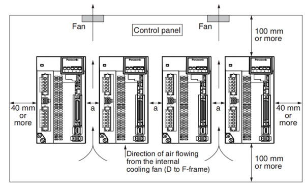
Install the driver properly to avoid a breakdown or an accident.
| Item | Conditions |
|---|---|
| Ambient temperature | 0 °C to 55 °C*1 (free from freezing) |
| Ambient humidity | 20% to 85% RH (free from condensation) |
| Storage temperature *1 | -20 °C to 65 °C (Max. temperature guarantee: 80 °C for 72 hours free from condensation *2) |
| Storage humidity | 20% to 85% RH (free from condensation *2) |
| Vibration | Lower than 5.88 m/s2, 10Hz to 60Hz (Do not continuously use the driver for a long time at the resonance point.) |
| Altitude | Lower than 1000m |
*1 Extreme temperatures are permissible only for short period such as during transportation.
*2 Air containing water vapor will become saturated with water vapor as the temperature falls, causing dew.
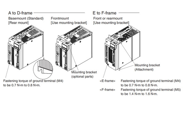
Note → It is recommended to use the conductive paint when you make your own mounting brack-et, or repaint after peeling off the paint on the machine for installing the products, in order to make noise countermeasure.
Caution →
Related page → •P. 1-7 "Specifications" • P.1-24 "Installation of motor"
• P.7-78 "Dimensions of driver"
•P.7-141 "Mounting bracket"
Determine the fundamental permissible current according to the cable conductor material (example: stranded copper wire). (For the purpose
of the example, the ampere indicated by █ is selected from the table right.)
Next, determine the number of conductors. (In this example, the cable contains 4 conductors (3 + ground).) Determin the applicable permissible
current using the following formula.
Applicable permissible current
= funcamental permissible current x current reduction coefficient x current correction coefficient
= 37 x 0.7 x 1.414
= 36.6(A)
This permissible value is larger than 35A to be carried though the cable. Therefore, according to the list of recommended eco-cables, the cable to be selected for the cable with nominal cross section 3.5 mm2 is a polyethylene-insulatd heat-resistant 4-conductor power cable having 13.5mm finish O.D. (approx. 14.5 mm with shield).
| Stranded conductor (nominal cross section: mm2) | Copper wire (unit: A) |
|---|---|
| 2 to 3.5 (excl.) | 27 |
| █ 3.5 to 5.5 (excl.) | 37 |
| 5.5 to 8 (excl.) | 49 |
| 8 to 14 (excl.) | 61 |
| 14 to 22 (excl.) | 88 |
| 11 to 30 (excl.) | 115 |
| 30 to 38 (excl.) | 139 |
| 38 to 60 (excl.) | 162 |
| 60 to 100 (excl.) | 217 |
| 100 to 150 (excl.) | 298 |
| 150 to 200 (excl.) | 395 |
| No. of wires in a tube | Coefficient |
|---|---|
| ©Up to 3 | 0.70 |
| 4 | 0.63 |
| 5 or 6 | 0.56 |
| 7 to 15 | |
| 16 to 40 | 0.43 |
| 41 to 60 | 0.39 |
| 61 or more | 0.34 |
Wire category: 4-conductor polyethylene-insulated power cable with heat-resistant polyethylene sheath (Standard: EM JIS C 3605) Maximum permissible temperature: 90 °C
| Conductor | Insulation thickness (mm) | Sheath thickness (mm) | (Reference) Finished O.D.(mm) | Max conductor resistance (20 °C)(W/km) | Test voltage (V/1 min.) | Minimum insulation resistance (MW.km) | (Reference) Approx. mass (kg/km) | ||
|---|---|---|---|---|---|---|---|---|---|
| Nominal cross section (mm2) | Structure or shape (wires/mm2) | Outside diameter (mm) | |||||||
| 2 | 7/0.6 | 1.8 | 0.8 | 1.5 | 12.0 | 9.42 | 1500 | 2500 | 170 |
| 3.5 | 7/0.8 | 1.8 | 0.8 | 1.5 | 13.5 | 5.30 | 1500 | 2500 | 250 |
| 5.5 | 7/1.0 | 3.0 | 1.0 | 1.5 | 16.0 | 3.40 | 1500 | 2500 | 360 |
| 8 | 7/1.2 | 3.6 | 1.0 | 1.5 | 17.0 | 2.36 | 1500 | 2000 | 475 |
| 14 | Circular compression | 4.4 | 1.0 | 1.5 | 19.0 | 1.34 | 2000 | 1500 | 730 |
| 22 | Circular compression | 5.5 | 1.2 | 1.6 | 23 | 0.849 | 2000 | 1500 | 1100 |
| 38 | Circular copmpression | 7.3 | 1.2 | 1.8 | 28 | 0.419 | 2500 | 1500 | 1800 |
| 60 | Circular compression | 9.3 | 1.5 | 2.0 | 35 | 0.311 | 2500 | 1500 | 2790 |
| 100 | Circular compression | 12.0 | 2.0 | 2.4 | 44 | 0.187 | 2500 | 1500 | 4630 |
| 150 | Circular compression | 14.7 | 2.0 | 2.6 | 51 | 0.124 | 3000 | 1000 | 6710 |
| 200 | Circular compression | 17.0 | 2.5 | 2.9 | 60 | 0.0933 | 3000 | 1500 | 8990 |
Caution → Shield will increase finish outside diameter by approx. 1mm.
Note → • Appropriate cable should be selected to have sufficient allowace of parameters such as operating ambient temperature
and current.
• Current reduction coefficient, fundamental permissible current, etc., stated on this page are subject to change due to e.g. standard revision. Consult cable manufacturers for the latest information.
Install the motor properly to avoid a breakdown or an accident.
Since the conditions of location affect a lot to the motor life, select a place which meets the conditions below.
| Item | Conditions | |
|---|---|---|
| Ambient temperature *1 | 0 °C to 40 ° C (free from freezing) | |
| Ambient humidity | 20% to 85% RH (free from condensation) | |
| Storage temperature*2 | -20 °C to 65 °C (Max. temperature guarantee: 80 °C for 72 hours free from condensation *4) | |
| Storage humidity | 20% to 85% RH (free from condensation *4) | |
| Vibration | Motor only | Lower than 49 m/s2 (5G) at running, 24.5 m/s2 (2.5G) at stall |
| Impact | Motor only | Lower than 98 m/s2 (10G) |
| Enclosure rating | Motor only (Connector type) | IP67 (except rotating portion of output shaft and connecting pin part of the motor connector and the encoder connector)*3 |
| Motor only (Leadwire type) | IP65 (except rotating portion of output shaft and connecting pin part of the motor connector and the encoder connector) *3 | |
| Altitude | Lower than 1000m | |
*1 Ambient temperature to be measured at 5 cm away from the motor.
*2 Permissible temperature for short duration such as transportation.
*3 These motors conform to the test conditions specified in EN standards (EN60529, EN60034-5), Do not use these motors in application where water
proof performance is required such as continuous wash-down operation.
*4 Air containing water vapor will become saturated with water vapor as the temperature falls, causing dew.
Note → For permissible load of each model, refer to P.1-26, "Permissible Load at Output Shaft".
Related page → • P.1-20 "Installation of driver" • P.1-24 "Permissible Load at Output Shaft" • P.7-84 "Dimensions of motor"
When wiring cable bear, take the following precautions:
The bend radius of the cable must be 10 times or more its finish outside diameter. (For finish outside diameter, refer to P.1-19
how to Install, "Relationship between Wire Diameter and Permissible Current" and associated tables.)
Do not fix or bundle wires in the cable bear.
When securing the cable, fix it only at non-movable ends of the cable bear where the cable is free from any stress (e.g. tension).
(Avoid tight lock.)
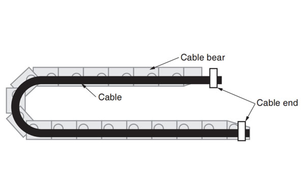
Caution → Do not keep the cable loosened (too long) or under tension (too short). Otherwise, the sheath will be cracked by internal wall of the cable bear, tangled by other cable, etc., Causing unpredictable troubles.
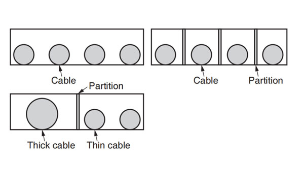
Keep the cable free from twists or kinks. Distorted cable will cause loose connection, lowering performance and reliability.
Place cables on a flat surface in parallel without bringing them into contact with each other and measure the dimension necessary to cover
these cables. Then select a cable bear which is wider than the measured dimension.
The lamination factor of cables should be lower than 60% (Recommended factor is 30% or below).
Do not run smaller and larger size cables in the same cable bear. Thin cables may break under the pressure of thick cables. If it is necessary
to mix cables of different size, isolate them by using suitable seperating material such as partition.
[Wiring arrangement in cable bear - example]

HD210LDY -- HaiDa Hybrid Injection Molding Machine
| No. | Name | Value |
|---|---|---|
| 1 | Clamping Force | 2100 kN |
| 2 | Shot Weight | 326 g |
| 3 | Shot Speed | 200 mm/s |
| 4 | Screw Diameter | 45 mm |
| 5 | Opening Stroke | 500 mm |
| 6 | Space Between Tie Bars | 530 x 530 mm |
| 7 | Mold Thickness (Min) | 200 mm |
| 8 | Mold Thickness (Max) | 550 mm |
| 9 | Pumper Motor | 90 kW |
| 10 | Heating Capacity | 16 kW |

The SWITEK side entry petri dish packing system is a custom made automation system for the stable production of laboratory consumable plastic petri dish with the picking robot, the petri dish assembly, stacking, packing unit etc. integrated as auniformed system for the efficient and stable production of the petri dish. The system can be custome made for a petri dish mold layout design of 2+2, 4+4, 6+6, 8+8 etc.


Mold Layout Deisgn

Sleeve Size for Package with Vacuum Request

Sleeve Size for Package without Vacuum Request

Sleeve (With Mark) Size for Package with Vacuum Request

Sleeve (With Mark) Size for Package without Vacuum Request
I think you'll have an overall understanding about the SWITEK top/side entry petri dish packing system. If you still have any other question about it or need any help in your petri dish production project, please feel free to contact SWITEK laboratory consumable plastic parts injection molding solutions team for more information.
HuangYanZheng©Copy Right


