
sales06@switek.biz

+86 186 5927 5869

Subscript to Us
sales06@switek.biz
+86 186 5927 5869
Subscript to Us
Keywords:Panasonic A6 Servo Installation Instruction, Panasonic A6 Driver, Panasonic A6 Series Servo Motor Manual
To change the monitor display setting, select the display option to be changed from "
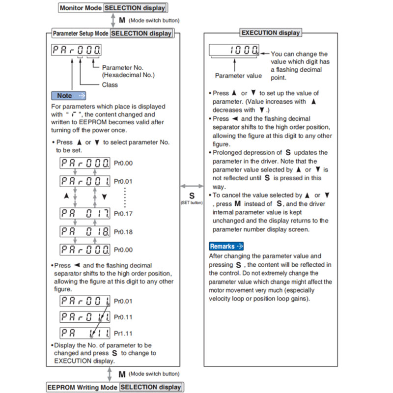
Note → • After setting up parameters, return to SELECT mode, referring to structure of each mode (P.4-42).
• Each parameter has a limit in number of places for upper-shifting.
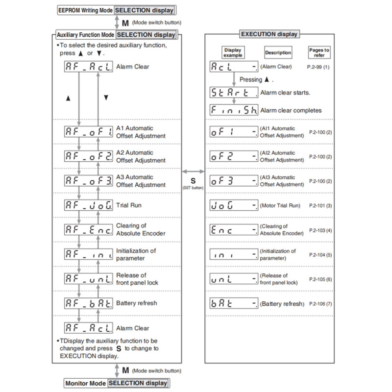
This function releases the current alarm status. Certain alarms will persist. If this is the case, refer to P.6-2 "When in Trouble - Protective Function".
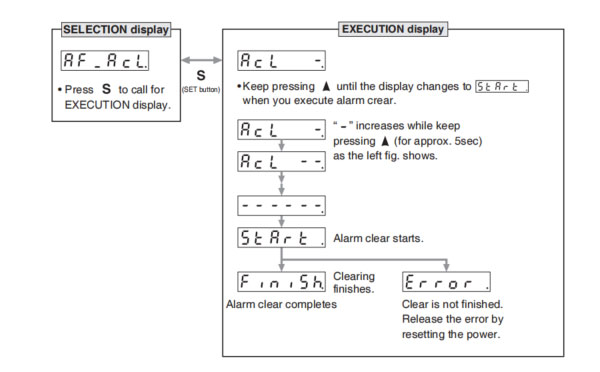
Note → • After alarm cleaning, return to SELECTION display, referring to structure of each mode (P.2-76).
This function automatically ajusts offset setting of analog input.
Analog input 1 (Al1)……Pr4.22 (Analog input 1(Al1) offset setup)
Analog input 2 (Al2)……Pr4.25 (Analog input 2(Al2) offset setup)
Analog input 3 (Al3)……Pr4.28 (Analog input 3(Al3) offset setup)
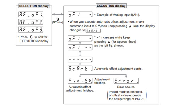
Remarks → • You cannot write the data only by executing automatic offset adjustment. Execute a writing to EEPROM when you need to reflect the result afterward.
Note → • After completion of the automatic offset adjustment, return to SELECTION display by referring to P.2-76 "Structure of Each Mode".
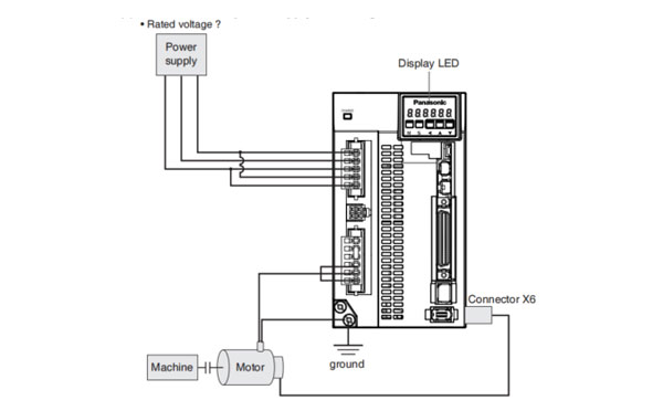
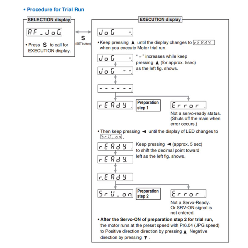
You can make a trial run (JOG run) without connecting the Connector, Connector X4 to the host controller such as PLC.
(1) Inspection on wiring
You can clear multi-turn data of the absolute encoder.
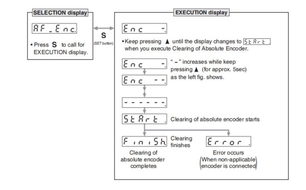
Note → • After clearing of absolute encoder finishes, return to SELECTION display, referring to structure of each mode (P.2-76).
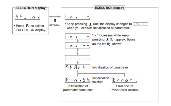
Initialize the parameter.
Release the front panel lock setting.
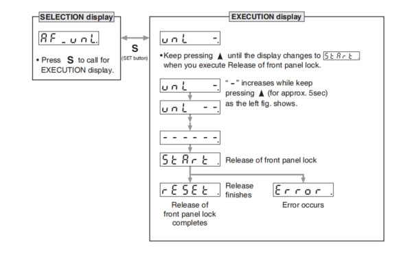
Note → • After release of front panel lock finishes, return to SELECTION display, referring to structure of each mode (P.2-76).
Battery refresh action is conducted.
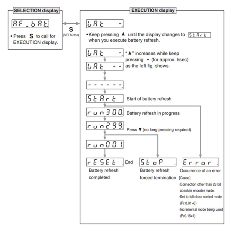
Note 1) When running Battery refresh, Battery alarm may occur in that case, please run the clear Battery alarm.
Note → • After release of front panel lock finishes, return to SELECTION display, referring to structure of each mode (P.2-76).

HD130LDY -- HaiDa Hybrid Injection Molding Machine
| No. | Name | Value |
|---|---|---|
| 1 | Clamping Force | 1300 kN |
| 2 | Shot Weight | 122 g |
| 3 | Shot Speed | 200 mm/s |
| 4 | Screw Diameter | 32 mm |
| 5 | Opening Stroke | 380 mm |
| 6 | Space Between Tie Bars | 420 x 420 mm |
| 7 | Mold Thickness (Min) | 150 mm |
| 8 | Mold Thickness (Max) | 450 mm |
| 9 | Pumper Motor | 49 kW |
| 10 | Heating Capacity | 7.5 kW |

The SWITEK side entry petri dish packing system is a custom made automation system for the stable production of laboratory consumable plastic petri dish with the picking robot, the petri dish assembly, stacking, packing unit etc. integrated as auniformed system for the efficient and stable production of the petri dish. The system can be custome made for a petri dish mold layout design of 2+2, 4+4, 6+6, 8+8 etc.


Mold Layout Deisgn

Sleeve Size for Package with Vacuum Request

Sleeve Size for Package without Vacuum Request

Sleeve (With Mark) Size for Package with Vacuum Request

Sleeve (With Mark) Size for Package without Vacuum Request
I think you'll have an overall understanding about the SWITEK top/side entry petri dish packing system. If you still have any other question about it or need any help in your petri dish production project, please feel free to contact SWITEK laboratory consumable plastic parts injection molding solutions team for more information.
HuangYanZheng©Copy Right


