
sales06@switek.biz

+86 186 5927 5869

Subscript to Us
sales06@switek.biz
+86 186 5927 5869
Subscript to Us
Keywords:Panasonic A6 Servo Installation Instruction, Panasonic A6 Driver, Panasonic A6 Series Servo Motor Manual
In the applications where the motor drives the vertical axis, this brake would be used to hold and prevent the work (moving load) from falling by gravity while the power to the servo is shut off.
The following shows the example when the brake is controlled by using the brake release output signal (BRK-OFF) of the driver.
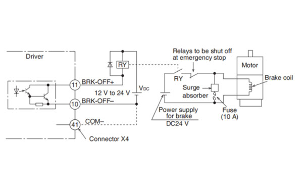
Note → 1. The Brake coil has no polarity.
Caution → 2. Power supply for the brake to be provided by customer. Do not co-use the power supply for the brake and for the control signals (VDC).
3. Install a surge absorber as the above Fig. shows to suppress surge voltage generated by ON/OFF action of the relay (RY). When you use a diode, note that the time from the brake release to brake engagement is slower than that of the case of using a surge absorber.
4. For a surge absorber, refer to P.7-146, "Recommended Components" of supplement.
5. Recommended components are specified to measure the brake releasing time.
Reactance of the cable varies depending on the cable length, and it might generate surge voltage.
Select a surge absorber so that relay coil voltage (max. rating:30V, 50mA) and terminal voltage may not exceed the rating.
Note →
| Motor series | Motor output | Static friction torque N*m | Rotor inertia x 10-4kg*m2 | Engaging time ms | Releasing time ms | Exciting current DC A (at cool-off) | Releasing voltage | Permissible work (J) per one braking | Permissible total work x 103J | Permissible angular acceleration rad/s2 |
|---|---|---|---|---|---|---|---|---|---|---|
| MSMF | 50 W, 100W | 0.294 or more | 0.002 | 35 or less | 20 or less | 0.30 | DC1V or more | 39.2 | 4.9 | 30000 |
| 200 W, 400 W | 1.27 or more | 0.018 | 15 or less | 50 or less | 0.36 | 137 | 44.1 | |||
| 750 W | 2.45 or more | 0.075 | 70 or less | 20 or less | 0.42 | 196 | 147 | |||
| 1.0 kW (☐80) | 3.80 or more | 185 | 80.0 | |||||||
| 1.0kW(☐100), 1.5kW, 2.0kW | 8.0 or more | 0.175 | 50 or less | 15 or less | 0.81 | DC2 V or more | 600 | 50 | 10000 | |
| 3.0 kW | 12.0 or more | 80 or less | 900 | |||||||
| 4.0 kW | 16.2 or more | 1.12 | 110 or less | 50 or less | 0.90 | 1470 | 2160 | |||
| 5.0 kW | 22.0 or more | 1545 | 2000 | |||||||
| MQMF | 100 W | 0.39 or more | 0.018 | 15 or less | 20 or less | 0.30 | DC1 V or more | 105 | 44.1 | 3000 |
| 200 W, 400 W | 1.6 or more | 0.075 | 70 or less | 0.36 | 185 | 80.0 | ||||
| MDMF | 1.0kW, 1.5kW, 2.0kW | 13.7 or more | 1.12 | 100 or less | 50 or less | 0.79 | DC2 V or more | 1470 | 2160 | 10000 |
| 3.0 kW | 22.0 or more | 110 or less | 0.90 | 1545 | 2000 | |||||
| 4.0 kW | 25.0 or more | 4.7 | 80 or less | 25 or less | 1.29 | 1800 | 3000 | 5440 | ||
| 5.0 kW | 44.1 or more | 4.1 | 150 or less | 30 or less | 3100 | 5108 | ||||
| MGMF | 850 W, 1.3kW, 1.8 kW | 13.7 or more | 1.12 | 100 or less | 50 or less | 0.79 | DC2 V or more | 1470 | 2160 | 10000 |
| 2.4kW | 25.0 or more | 4.7 | 80 or less | 25 or less | 1.29 | 1800 | 3000 | 5440 | ||
| 2.9 kW | ||||||||||
| 4.4 kW | 44.1 or more | 3.93 | 150 or less | 30 or less | 3100 | 5108 | ||||
| MHMF | 50 W, 100 W | 0.38 or more | 0.002 | 35 or less | 20 or less | 0.30 | DC1 V or more | 39.2 | 4.9 | 30000 |
| 200 W, 400 W | 1.6 or more | 0.018 | 50 or less | 0.36 | 105 | 44.1 | ||||
| 750 W, 1.0kW (☐80) | 3.8 or more | 0.075 | 70 or less | 0.42 | 185 | 80.0 | ||||
| 1.0kW(☐130), 1.5kW | 13.7 or more | 1.12 | 100 or less | 50 or less | 0.79 | DC2 V or more | 1470 | 2160 | 10000 | |
| 2.0 kW, 3.0kW, 4.0kW | 25 or more | 4.7 | 80 or less | 25 or less | 1.29 | 1800 | 3000 | 5440 | ||
| 5.0 kW | 44.1 or more | 4.1 | 150 or less | 30 or less | 3100 | 5108 |

HD130LDY -- HaiDa Hybrid Injection Molding Machine
| No. | Name | Value |
|---|---|---|
| 1 | Clamping Force | 1300 kN |
| 2 | Shot Weight | 147 g |
| 3 | Shot Speed | 200 mm/s |
| 4 | Screw Diameter | 36 mm |
| 5 | Opening Stroke | 380 mm |
| 6 | Space Between Tie Bars | 420 x 420 mm |
| 7 | Mold Thickness (Min) | 150 mm |
| 8 | Mold Thickness (Max) | 450 mm |
| 9 | Pumper Motor | 49 kW |
| 10 | Heating Capacity | 7.5 kW |

The SWITEK side entry petri dish packing system is a custom made automation system for the stable production of laboratory consumable plastic petri dish with the picking robot, the petri dish assembly, stacking, packing unit etc. integrated as auniformed system for the efficient and stable production of the petri dish. The system can be custome made for a petri dish mold layout design of 2+2, 4+4, 6+6, 8+8 etc.


Mold Layout Deisgn

Sleeve Size for Package with Vacuum Request

Sleeve Size for Package without Vacuum Request

Sleeve (With Mark) Size for Package with Vacuum Request

Sleeve (With Mark) Size for Package without Vacuum Request
I think you'll have an overall understanding about the SWITEK top/side entry petri dish packing system. If you still have any other question about it or need any help in your petri dish production project, please feel free to contact SWITEK laboratory consumable plastic parts injection molding solutions team for more information.
HuangYanZheng©Copy Right


