
sales06@switek.biz

+86 186 5927 5869

Subscript to Us
sales06@switek.biz
+86 186 5927 5869
Subscript to Us
Keywords:Panasonic A6 Servo Motor, Panasonic A6 Servo Motor Driver, Panasonic A6 Servo Motor setting instruction
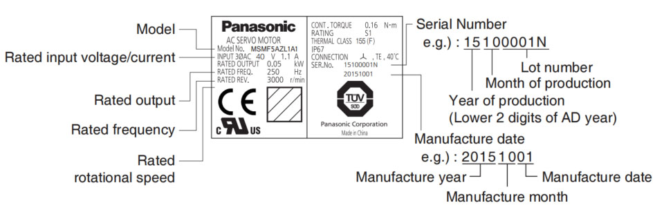
The name plate of the servo motor and driver provide an overall guideline of the motor and driver, here in this chapter we're explaining in detail the meaning of the datas on the name plate of the Panasonic A6 series of AC servo and motor.
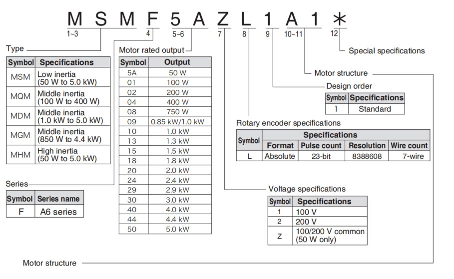
MSMF (Below ☐80)
| Symbol | Shaft | Holding brake | Oil seal | Motor I/F | |||||
|---|---|---|---|---|---|---|---|---|---|
| 10 dig | 11 dig | Round | Key way Threaded | Without | With | Without | With | Connector type | Leadwire type |
| A | 1 | • | • | • | • | ||||
| A | 2 | • | • | • | • | ||||
| B | 1 | • | • | • | • | ||||
| B | 2 | • | • | • | • | ||||
| C | 1 | • | • | • | • | ||||
| C | 2 | • | • | • | • | ||||
| D | 1 | • | • | • | • | ||||
| D | 2 | • | • | • | • | ||||
| S | 1 | • | • | • | • | ||||
| S | 2 | • | • | • | • | ||||
| T | 1 | • | • | • | • | ||||
| T | 2 | • | • | • | • | ||||
| U | 1 | • | • | • | • | ||||
| U | 2 | • | • | • | • | ||||
| V | 1 | • | • | • | • | ||||
| V | 2 | • | • | • | • | ||||
Note → • For details of specific model, refer to the Dimensions of Supplement.
Related page → • P.1-19 "Check of the Combination of the Driver and Motor" • P.7-84 to 7-107 "Dimensions of motor"
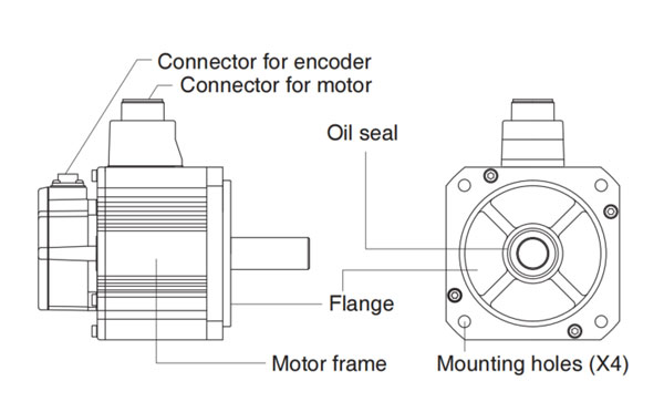
Motor structure
MQMF, MHMF (Below ☐80)
| Symbol | Shaft | Holding brake | Oil Seal | Motor I/F | ||||||
|---|---|---|---|---|---|---|---|---|---|---|
| 10 dig | 11 dig | Round | Key way Threaded | Without | With | Without | With | With (Protective lip) | Connector type | Leadwire type |
| A | 1 | • | • | • | • | |||||
| A | 2 | • | • | • | • | |||||
| B | 1 | • | • | • | • | |||||
| B | 2 | • | • | • | • | |||||
| C | 1 | • | • | • | • | |||||
| C | 2 | • | • | • | • | |||||
| C | 3 | • | • | • | • | • | ||||
| C | 4 | • | • | • | • | • | ||||
| D | 1 | • | • | • | • | |||||
| D | 2 | • | • | • | • | |||||
| D | 3 | • | • | • | ||||||
| D | 4 | • | • | • | ||||||
| S | 1 | • | • | • | • | |||||
| S | 2 | • | • | • | • | |||||
| T | 1 | • | • | • | • | |||||
| T | 2 | • | • | • | • | |||||
| U | 1 | • | • | • | • | |||||
| U | 2 | • | • | • | • | |||||
| U | 3 | • | • | • | • | |||||
| U | 4 | • | • | • | • | |||||
| V | 1 | • | • | • | • | |||||
| V | 2 | • | • | • | • | |||||
| V | 3 | • | • | • | • | |||||
| V | 4 | • | • | • | • | |||||
MSMF, MDMF, MGMF, MHMF (Above ☐80)
| Symbol | Shaft | Holding brake | Oil seal | Motor I/F | |||||
|---|---|---|---|---|---|---|---|---|---|
| 10 dig | 11 dig | Round | Key way Threaded | Without | With | With | With (Protective lip) | Connector JN2 | Connector JL10 |
| C | 5 | • | • | • | • | ||||
| C | 6 | • | • | • | • | ||||
| C | 7 | • | • | • | • | ||||
| C | 8 | • | • | • | • | ||||
| D | 5 | • | • | • | • | ||||
| D | 6 | • | • | • | • | ||||
| D | 7 | • | • | • | • | ||||
| D | 8 | • | • | • | • | ||||
| G | 5 | • | • | • | • | ||||
| G | 7 | • | • | • | • | ||||
| G | 8 | • | • | • | • | ||||
| H | 5 | • | • | • | • | ||||
| H | 6 | • | • | • | • | ||||
| H | 7 | • | • | • | • | ||||
| H | 8 | • | • | • | • | ||||
Note → • For details of specific model, refer to the Dimensions of Supplement.
Related page → • F.1-19 "Check of the Combination of the Driver and the Motor" • P.7-84 to 7-107 "Dimensions of motor"
•MSMF 50 W to 1.0kW (☐80)
•MHMF 50 W to 1.0kW (☐80)
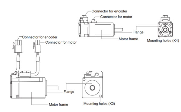
•MQMF 100 W to 400W
e.g.): Low inertia type (MSMF series, 50W), High inertia type (MHMF series, 50W)
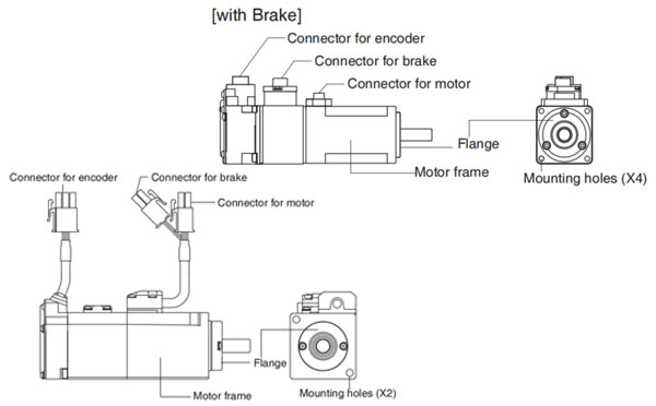
•MSMF 1.0 kW (☐100) to 5.0kW
•MDMF 1.0 kW to 5.0kW
•MGMF 850 W to 4.4kW
•MHMF 1.0 kW (☐130) to 5.0 kW
e.g.): Middle inertia type (MDMF series, 1.0 kW)
Note → For details of specific model, refer to the Dimensions of Supplement. (P.7-84 to 7-107)

HD130LDY -- HaiDa Hybrid Injection Molding Machine
| No. | Name | Value |
|---|---|---|
| 1 | Clamping Force | 1300 kN |
| 2 | Shot Weight | 122 g |
| 3 | Shot Speed | 200 mm/s |
| 4 | Screw Diameter | 32 mm |
| 5 | Opening Stroke | 380 mm |
| 6 | Space Between Tie Bars | 420 x 420 mm |
| 7 | Mold Thickness (Min) | 150 mm |
| 8 | Mold Thickness (Max) | 450 mm |
| 9 | Pumper Motor | 49 kW |
| 10 | Heating Capacity | 7.5 kW |

The SWITEK side entry petri dish packing system is a custom made automation system for the stable production of laboratory consumable plastic petri dish with the picking robot, the petri dish assembly, stacking, packing unit etc. integrated as auniformed system for the efficient and stable production of the petri dish. The system can be custome made for a petri dish mold layout design of 2+2, 4+4, 6+6, 8+8 etc.


Mold Layout Deisgn

Sleeve Size for Package with Vacuum Request

Sleeve Size for Package without Vacuum Request

Sleeve (With Mark) Size for Package with Vacuum Request

Sleeve (With Mark) Size for Package without Vacuum Request
I think you'll have an overall understanding about the SWITEK top/side entry petri dish packing system. If you still have any other question about it or need any help in your petri dish production project, please feel free to contact SWITEK laboratory consumable plastic parts injection molding solutions team for more information.
HuangYanZheng©Copy Right


