switek email

sales06@switek.biz

switek whatsapp

+86 186 5927 5869

Subscript to Us

.
Panasonic A6 Motor & Driver Instruction 3.1.4 Outline of mode — Full-closed Control Mode

HIGH SPEED IML ROBOT

Keywords:Panasonic A6 Servo Installation Instruction, Panasonic A6 Driver, Panasonic A6 Series Servo Motor Manual

Panasonic A6 Motor & Driver Instruction 3.1.4 Outline of mode — Full-closed Control Mode

Abstract

In this full-closed control, you can make a position control by using a external scale mounted externally which detects the position directly and feeds it back. With this control, you can control without being affected by the positional variation due to the ball screw error or temperature and you can expect to achieve a very high precision positioning in sub-micron order.

panasonic a6 servo motor

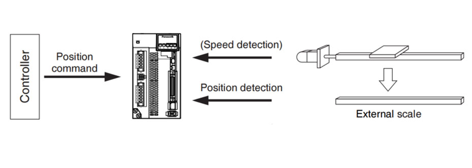
We recommend the external scale division ratio of 1/40 ≤ External scale division ration ≤ 1280

  1. Enter the command pulses making the external scale as a reference.
    If the command pulses do not match to the external scale pulses, use the command divivion/multiplication function (Pr0.09 to Pr0.10) and setup so that the command pulses after division/multiplication is based on the external scale reference.
  2. The A5 series supports the external scale of A- and B-phase output type and serial communication type. Initialize the parameters according to the following procedures and write to EEPROM and turn on power.
  3. When using a scale of A- and B- phase output type, correctly connect it so that the totating direction of the motor (CW/CCW) and A-phase and B-phase of the external scale have the following relationship.
    panasonic a6 servo motor
<How to make an initial setup of parameters related to external scale>
  1. Turn on the power after checking the wiring.
  2. Check the values (initial) feedback pulse sum and external feedback pulse sum with the front panel.
  3. Move the work and check the travel from the initial values of the above (2).
  4. If the travel of the feedback pulse sum and the external scale feedback pulse sum are reversed in positive and negative, set up the reversal of external scale direction (Pr3.26) to 1.
  5. Set up the external scale division ratio Pr3.24/Pr3.25 based on the design values.
    External scale division ratio = (Encoder resolution per motor revolution [pulse])/(External scale's resolution per motor revolution [pulse]) = Pr3.24/Pr3.25
    If a wrong scale is applied, difference between the position calculated by using encoder feedback pulses and the position calculated by using external scale pulses as moving distance increases: Larger difference will cause excessive deviation error protect.
  6. Set up appropriate value of hybrid deviation excess (Pr3.28) in command unit, in order to avoid the damage to the machine.
    * A6-sereies driver calculates the difference between the encoder position and the external scale position as hybrid deviation, and is used to prevent the machine runaway or damage in case of the external scale breakdown or when the motor and the load is disconnected.
    If the hybrid deviation excess range is too wide, detection of the breakdown or the disconnection will be delayed and error detection effect will be lost. If this is too narrow, it may detect the normal distortion between the motor and the machine under normal operation as an error.
    *When the external scale division ration is not correct, hybrid deviation excess error (Err25.0) may occur especially when the work travels long distance, even though the external scale and the motor position matches.
    In this case, widen the hybrid deviation excess range by matching the external sscale division ratio to the closest value.

•P.3-19 "Control Block Diagram" • P.3-22 "Wiring Diagram to the connector, X4" • P.3-35 "Inputs and outputs on connector X4" • P.4-6 to P.4-85 "Details of parameter"

Function
(1) Selection of external scale type

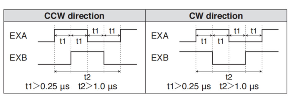
Select the type of external scale to be used.

• Relevant parameters

Parameter No. Title Range Function
Pr3.18 External scale selection 0 to 6 Select the type of external scale.
Pr3.26 Reversal of direction of external scale 0 to 3 Reverse the direction of external scale, feedback counter.

Note → For details of these parameters, refer to P.4-6 to P.4-85 "Details of parameter".

(2) Setup of external scale division ratio

Set up the division ratio of encoder resolution and external scale resolution.

• Relevant parameters

Parameter No. Title Range Function
Pr3.24 Numberator of external scalel division 0 to 223 Set up the numerator of the external scale dividing setup.
Pr3.25 Denominator of external scale division 0 to 223 Set up the Denominator of the external scale dividing setup.

For details of these parameters, refer to P.4-6 to P.4-85 "Details of parameter".

(3) Setup of hybrid excessive deviation

This function detects the positional difference between the motor (encoder) and load (external scale) and enables the hybrid excessive deviation protection if the differene exceeds Pr3.28 "Hybrid excessive deviation setup".
Hybrid excessive deviation is mainly caused by feedback scale error, wrong connection and loose connection between the motor and load.

• Relevant parameters

Parameter No. Title Range Function
Pr3.28 Hybrid deviation excess setup 1 to 227 You can setup the permissible gap (hybrid deviation) between the present motor position and the present external scale position.
Pr3.29 Hybrid deviation clear setup 0 to 100 As the motor turns the number of revolutions set by this parameter, the hybrid deviation is cleared to 0.

For details of these parameters, refer to P.4-6 to P.4-85 "Details of parameter".


Hybrid Injection Molding Machine for Laboratory Consumable Petri Dish Injection Molding -- HD170LDY-B
Haida hybrid Injection Molding Machine
HD170LDY-B

HD170LDY -- HaiDa Hybrid Injection Molding Machine

No. Name Value
1 Clamping Force 1700 kN
2 Shot Weight 147 g
3 Shot Speed 200 mm/s
4 Screw Diameter 36 mm
5 Opening Stroke 440 mm
6 Space Between Tie Bars 470 x 470 mm
7 Mold Thickness (Min) 200 mm
8 Mold Thickness (Max) 520 mm
9 Pumper Motor 56 kW
10 Heating Capacity 11 kW

Injection Automation Application -- Side Entry Petri Dishs Injection Molding Automation Solution
petri dish packing solution

SIDE ENTRY PETRI DISH PACKING SOLUTION

Introduction of SWITEK Side Entry Petri Dish Packing System

The SWITEK side entry petri dish packing system is a custom made automation system for the stable production of laboratory consumable plastic petri dish with the picking robot, the petri dish assembly, stacking, packing unit etc. integrated as auniformed system for the efficient and stable production of the petri dish. The system can be custome made for a petri dish mold layout design of 2+2, 4+4, 6+6, 8+8 etc.

Functional Units of SWITEK Top Entry Petri Dish Packing System
petri dish packing solution
  • (1) -- Side Entry Robotic Arm: The picking arm of the packing system in handling the picking of the petri dish from the injection molding machine and place them on the assembly unit.
  • (2) -- Injection Mold: The core injection unit to shape the petri dish, it can be 2+2, 4+4, 6+6, 8+8 configuragion of the petri covers and bottoms.
  • (3) -- Petri Dish Assembly Unit: Have the cover and bottom of the petri dish assembled and drop it on the conveyor.
  • (4) -- Sorting Conveyor: Lined the assembled petri dish sets for stacking before packing.
  • (5) -- Stacking Station: Have the well assembled petri dishes stacked up as requested (5/10/15/20/25 sets etc.).
  • (6) -- Petri Dish Packing Unit: Have the well stacked petri dish packed and sealed with optional function of vacuume the bag.
  • (7) -- Petri Dish Transfer Robot: Catch the well sealed petri dish bag and drop it to the conveyor.
  • (8) -- Petri Dish Dropping Conveyor: Deliver the well packed petri dish.
  • (9) -- Injection Molding Machine: The injection unit of the whole syste.

Installation Dimension of SWITEK Side Entry Petri Dish Packing System
petri dish packing solution

Productivity of SWITEK Side Entry Petri Dish Packing Solutions
    Vacuumed Sleeve Packing
  • 10 Sets/Bag --Injection Cycle time: 9s
  • 20 Sets/Bag --Injection cycle: 6s
  • 25 Sets/Bag --Injection Cycle: 5.5s
    Non-vacuumed Sleeve Packing
  • 10 Sets/Bag --Injection Cycle time: 6.5s
  • 20 Sets/Bag --Injection cycle: 6s
  • 25 Sets/Bag --Injection Cycle: 5.5s

Mold Layout Design & Sleeve Size for the Petri Dish Packing System
petri dish packing solution

Mold Layout Deisgn

petri dish packing solution

Sleeve Size for Package with Vacuum Request

petri dish packing solution

Sleeve Size for Package without Vacuum Request

petri dish packing solution

Sleeve (With Mark) Size for Package with Vacuum Request

petri dish packing solution

Sleeve (With Mark) Size for Package without Vacuum Request

I think you'll have an overall understanding about the SWITEK top/side entry petri dish packing system. If you still have any other question about it or need any help in your petri dish production project, please feel free to contact SWITEK laboratory consumable plastic parts injection molding solutions team for more information.


Email: sales06@switek.biz

WhatsApp

WeChat


Request for Quotation Now
Submit