switek email

sales06@switek.biz

switek whatsapp

+86 186 5927 5869

Subscript to Us

.
SWITEK IML Robot Instruction -- SigmaTek -- In Mold Safety Screen

High Speed Siden Entry IML Robot SW833-S6

SWITEK IML Robot Instruction -- SigmaTek -- In Mold Safety Screen

Abstract

With the control system developed by the Austria automatic company SIGMATEK GmbH & Co KG, SWITEK high speed side entry IML robot is providing a more efficient and outstanding performance for your quality bulk production of the IML Yogurt Cups.

1.Basic Screen

1.2.1 In Mold Safety Screen

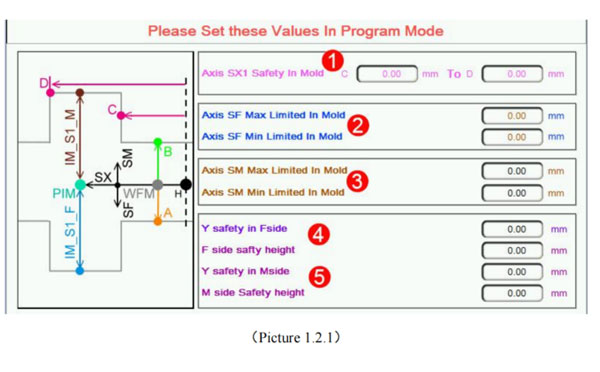
Click iml robot control system button into In Mold Safety screen, as the picture below 1.2.1;
Attention: Please Set these Values in program mode;
iml robot control system
  1. SX axis Safety In Mold:
    Said if SX Out Mold Safety signal is not reaction;
    1) if SX position in C (In Mold the minimum safe place) to D (In Mold the maximum safety place) range;
    2) if SX position is not in C and D, so SF/SM maximum running is not allow exceed standby point;
  2. SF axis max/min Limited In Mold:
    Said if SX Out Mold Safety signal is not reaction, SF Can run to maximum/minimum position.
  3. SM axis max/min Limited In Mold
    Said if SX Out Mold Safety signalis not reaction; SM Can run to maximum/minimum position.
  4. Y Safety in F-side FY:
    Within the range, FX axis can run; F-side safety height: FZ axis within the range, FX axis can run;
  5. M-side (MX/MY/MZ axis limiting condition) like as 4 set.

1.2.2 Standby Point Screen

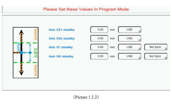
Click iml robot control system button to standby point screen as the picture below 1.2.2;
Attention: Please Set these Values in program mode
When modify the setting in this screen the Teach mode is needed;
iml robot control system

Standby position said robot in out-mold waiting for the injection molding machine module open, every axis position.
Use the option: This axis Whether to participate in standby movement. When choose to use, When standby running, the axis will run to the corresponding standby point position; When chose not to use, the axis is not affected by standby operation (continue to initial sstate action);
Seperate running options: Said when standby running of SF/SM, Whether with SX axis action; When choosing Separate running, the SX first run to the standby position, And then run SF/SM run to the standby point together (Precondition for the axis in standby movement).

1.2.3 Stack Parts Screen

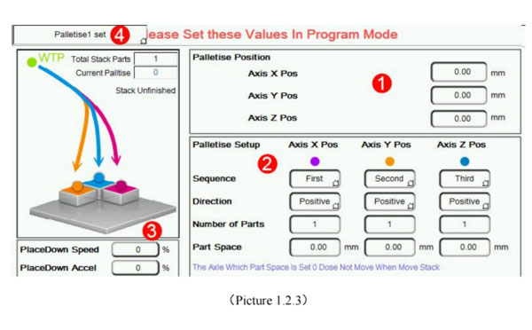
Click iml robot control system button to Stack Parts Screen as the picture below 1.2.3;

Attention: Please Set these Values in program mode;
iml robot control system
  1. Palletise Position: Axis X(FX/MX), Y(FY/MY), Z(FZ/MZ) Position.
  2. Palletise Setup:
    Sequence: Set X, Y, Z stacked sequence, First of all increase which direction.
    Direction: Set X, Y, Z direction, including the forward and reverse. The forward said axis position increase when stack, Whereas said axis position decrease;
    Number of Parts: Set X, Y, Z three directions placement number.
    Part Space: Spacing between adjacent two products;
  3. Stack Speed: Place down speed and place down accelerated speed can be set.
    Current Palltise: Program support 2 groups of different Settings of the stack, the corresponding stack group can call in the Program. Stacked case, please see accessory 1

1.2.4 Get Label Screen

Click iml robot control system button to get label screen as the picture below 1.2.4:
Attention: Please Set these Values in Program mode, get label case please see accessory 2.
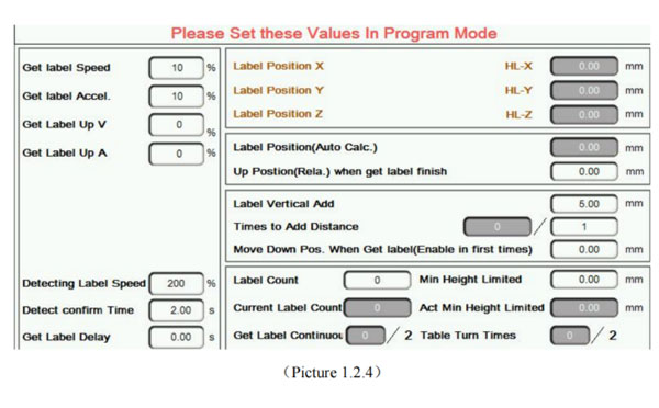
iml robot control system

1.2.5 Reset Setting

Click iml robot operating instruction button to Reset Setting screen as the picture below 1.2.5:
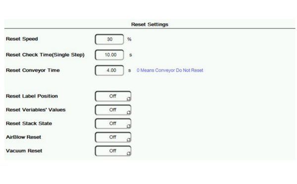
iml robot control system
  1. Reset Speed: When click the reset button, Several axis movement reset Speed, Setting can decide for themselves;
  2. Reset Conveyor Time: When reset, conveyor belt action time;
  3. Check Label when Cycle Start: Application in the case of getting label axis for the servo axis;
  4. Reset Check Time (Single Step): If single-step speed faster than setting setting When resetting, it will be alarm.
    Attention: Each axis reset sequence are those when the axis reference sequeence after starting up.


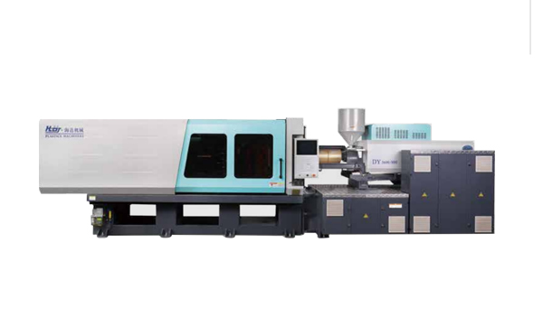
Hybrid Injection Molding Machine for Laboratory Consumable Petri Dish Injection Molding -- HD300KDY
Haida hybrid Injection Molding Machine
HD300KDY

HD300KDY -- HaiDa Hybrid Injection Molding Machine

No. Name Value
1 Clamping Force 3000 kN
2 Shot Weight 402 g
3 Shot Speed 350 mm/s
4 Screw Diameter 50 mm
5 Opening Stroke 550 mm
6 Space Between Tie Bars 590 x 590 mm
7 Mold Thickness (Min) 220 mm
8 Mold Thickness (Max) 600 mm
9 Pumper Motor 147 kW
10 Heating Capacity 21 kW

Injection Automation Application -- Side Entry Petri Dishs Injection Molding Automation Solution
petri dish packing solution

SIDE ENTRY PETRI DISH PACKING SOLUTION

Introduction of SWITEK Side Entry Petri Dish Packing System

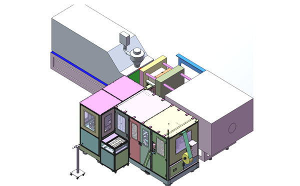
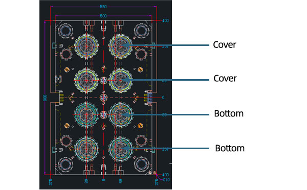
The SWITEK side entry petri dish packing system is a custom made automation system for the stable production of laboratory consumable plastic petri dish with the picking robot, the petri dish assembly, stacking, packing unit etc. integrated as auniformed system for the efficient and stable production of the petri dish. The system can be custome made for a petri dish mold layout design of 2+2, 4+4, 6+6, 8+8 etc.
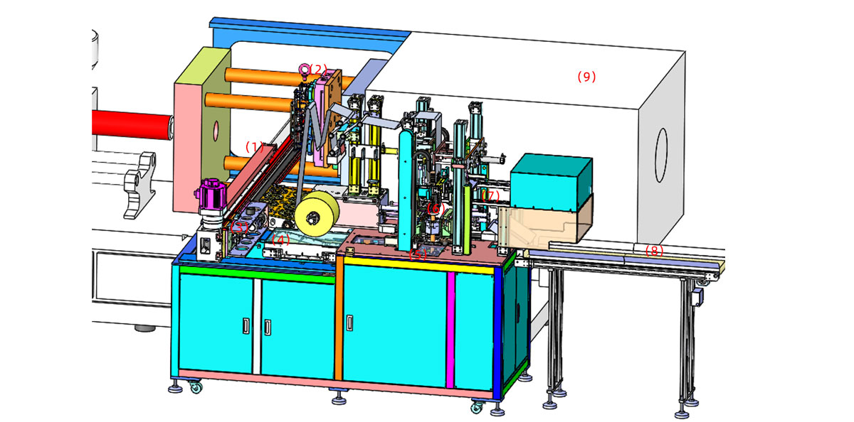
Functional Units of SWITEK Top Entry Petri Dish Packing System
petri dish packing solution
  • (1) -- Side Entry Robotic Arm: The picking arm of the packing system in handling the picking of the petri dish from the injection molding machine and place them on the assembly unit.
  • (2) -- Injection Mold: The core injection unit to shape the petri dish, it can be 2+2, 4+4, 6+6, 8+8 configuragion of the petri covers and bottoms.
  • (3) -- Petri Dish Assembly Unit: Have the cover and bottom of the petri dish assembled and drop it on the conveyor.
  • (4) -- Sorting Conveyor: Lined the assembled petri dish sets for stacking before packing.
  • (5) -- Stacking Station: Have the well assembled petri dishes stacked up as requested (5/10/15/20/25 sets etc.).
  • (6) -- Petri Dish Packing Unit: Have the well stacked petri dish packed and sealed with optional function of vacuume the bag.
  • (7) -- Petri Dish Transfer Robot: Catch the well sealed petri dish bag and drop it to the conveyor.
  • (8) -- Petri Dish Dropping Conveyor: Deliver the well packed petri dish.
  • (9) -- Injection Molding Machine: The injection unit of the whole syste.

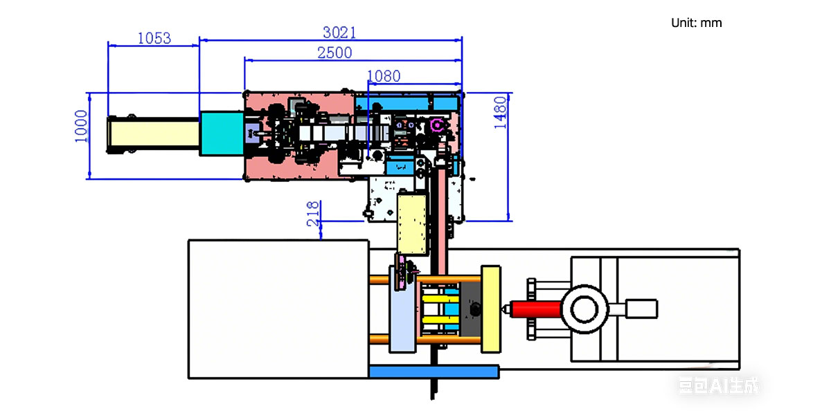
Installation Dimension of SWITEK Side Entry Petri Dish Packing System
petri dish packing solution

Productivity of SWITEK Side Entry Petri Dish Packing Solutions
    Vacuumed Sleeve Packing
  • 10 Sets/Bag --Injection Cycle time: 9s
  • 20 Sets/Bag --Injection cycle: 6s
  • 25 Sets/Bag --Injection Cycle: 5.5s
    Non-vacuumed Sleeve Packing
  • 10 Sets/Bag --Injection Cycle time: 6.5s
  • 20 Sets/Bag --Injection cycle: 6s
  • 25 Sets/Bag --Injection Cycle: 5.5s

Mold Layout Design & Sleeve Size for the Petri Dish Packing System
petri dish packing solution

Mold Layout Deisgn

petri dish packing solution

Sleeve Size for Package with Vacuum Request
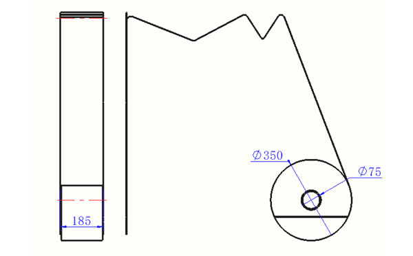
petri dish packing solution

Sleeve Size for Package without Vacuum Request
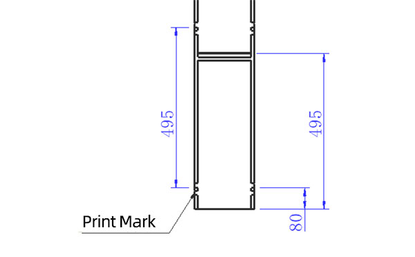
petri dish packing solution

Sleeve (With Mark) Size for Package with Vacuum Request
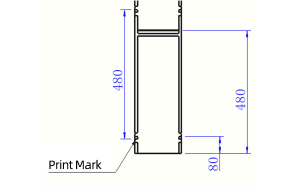
petri dish packing solution

Sleeve (With Mark) Size for Package without Vacuum Request

I think you'll have an overall understanding about the SWITEK top/side entry petri dish packing system. If you still have any other question about it or need any help in your petri dish production project, please feel free to contact SWITEK laboratory consumable plastic parts injection molding solutions team for more information.


Email: sales06@switek.biz

WhatsApp

WeChat


Request for Quotation Now
Submit