
sales06@switek.biz

+86 186 5927 5869

Subscript to Us
sales06@switek.biz
+86 186 5927 5869
Subscript to Us

With the control system developed by the Austria automatic company SIGMATEK GmbH & Co KG, SWITEK high speed side entry IML robot is providing a more efficient and outstanding performance for your quality bulk production of the IML Yogurt Cups.
4.1 Alarms
Click Alarms button. As shown in the below picture of 1.6.1:
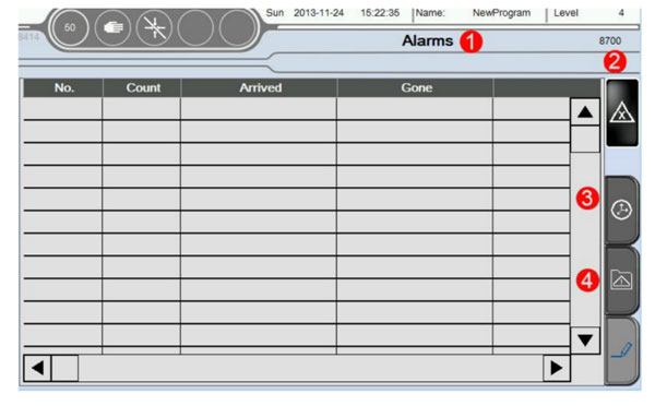
| No | Alarm | Illumination | Treatment |
|---|---|---|---|
| A004 to A015 | Axis Interior Min Limit | Indicates current actual limit is less than the set Min limit. | In the manual page, remove this axis to Min Limited Funcction/Servo Setup/Axis/**/Axis Assignment->Max Limited in program, actual limited must be more than this set value, suggestion for -1.00mm. |
| A021 to A032 | Axis interior Max limit | Indicates current actual limit more than the set Max limit | In the manual page, remove this axis to Max Limited Function/Servo Setup/Axis/**/Axis Assignment->Max Limited in program, actual limited must be less than this set value. This value is depended on the Mechanical Dimensions. |
| A041 to A052 | Axis position limit | Indicates axis' motion can not follow the speed of CNC instruction | -Function/Servo Setup/Axis/**/Axis Control Assignment-> Max limited deviation, the first value is set 10mm more than the second. The second show the current actual deviation, suggested to adjust driver's rigidity to decrease deviation. -Function/Servo Setup/Axis Assignment/**/Axis Control Assignment -> advance the value of KV, VU, suggested to advance 50 each time -adjust accelerated speed, Function/Servo Setup/Axis configuration |
| A061 to A072 | Axis Alarms | Indicates breakdown happens inthe current axis** | -Axis control module (CST 022/CNC 305/CNC 115 and so on) has not been tested -+24V/+5V power supply of Axis control module is abnormal -Check the corresponding limiting point configuration of I/O |
| A081 to A092 | Axis position Min limit | Indiccates that there is signal inputting in the Minimum limit sensor of current axis | -mechanical hand is located in the position beyond limit Check machine -misdescription happens in the transducer. Check transducer -Check the corresponding limiting point configuration of I/O |
| A101 to A112 | Axis position Max limit | Indicates that there is signal inputting in the Maximum limit sensor of currrent axis. | -mechanical hand is located in the position beyond limit. Check machine -misdescription happens in the transducer. Check ransducer -Check the corresponding point configuration of I/O |
| A121 | Emergency stop button Pressed down | Emergency stop of machine active on the Control panel. | -Rotate the Emergency stop of machine chockwise to loosen it/System Setup. function is , so this Emergency will not appear until Reboot; if check . Emergency disiappear automatically. -If Button Stop of hand controller virtual key is pressed down, reset this virtual key. |
| A122 | Pressure abnormal | pressure abnormal | Check pressure. Check wether or not pressure test has been turned on. |
| A123 | Emergency stop of machine active | Checked Emergency stop of machine put down |
|
| A124 | Safety equipment is abnormal | Machine safety door open |
|
| A125 | Quantity accomplished | Set quantity has been finished | Function/produce setup page->Quantity Setup |
| A126 | Reject part reaches setting limit | Amount of reject part has reached the number of set alarms | function/produce setup page - > Reject Alarm Interval |
| A127 | Cycle time overtime | Cyclical time exceeds the safety time scope. | function/produce setup page -> motion monitor time; 0 do not means monitor. |
| A128 | Fixture abnormal | Fixture motion beyond the set time of monitor |
|
| A129 | Module Open/Close signal abnormal | Conflict between Module Open and Module Close |
|
| A130 | Vacuum abnormal | Monitor of Vacuum exceed the set monitor time. |
|
| A131 | Division by zero error | Set parameter has been divided by 0. | Check whether set parameter has been divided by 0. Set parameter is too small. |
| A133 | Module Open Interval Time | Interval is too short between two Module Open |
|
| A141 to A149 | Baseboard slot modulel error | The order error in the second module Baseboard …… the order error in the ninth module Baseboard |
|
| A150 | CIV512 module error | Order of CIV 512 module tests wrong. |
|
| A151 A152 | Driver module | Order of Driver SDD/MDD tests wrong. Driver 1: PLC varan bus connects with the driver firstly; Driver 2: bus connects with this driver secondly |
|
| A161 | Module Open pattern Interval abnormal | Interval between the two Module Open Receive signal is too short |
|
| A162 | The label paper shortage | System receives the signal of label paper shortage |
|
| A163 | VBC error | The order of VBC module is tested wrong |
|
| A171 to A203 | Motion overtime | Automatic running, the motion time of corresponding axis exceeds safety time. |
|
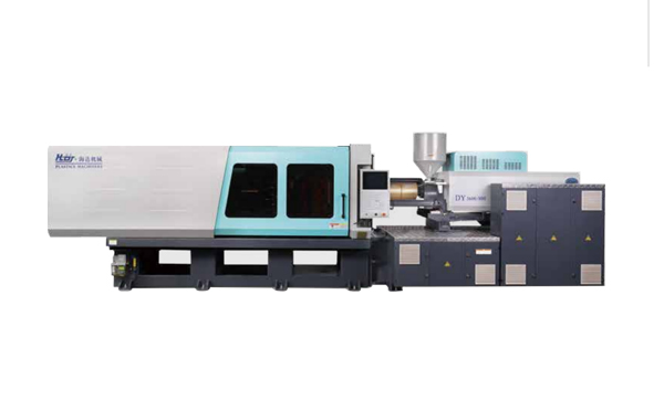
HD300KDY -- HaiDa Hybrid Injection Molding Machine
| No. | Name | Value |
|---|---|---|
| 1 | Clamping Force | 3000 kN |
| 2 | Shot Weight | 402 g |
| 3 | Shot Speed | 350 mm/s |
| 4 | Screw Diameter | 50 mm |
| 5 | Opening Stroke | 550 mm |
| 6 | Space Between Tie Bars | 590 x 590 mm |
| 7 | Mold Thickness (Min) | 220 mm |
| 8 | Mold Thickness (Max) | 600 mm |
| 9 | Pumper Motor | 147 kW |
| 10 | Heating Capacity | 21 kW |
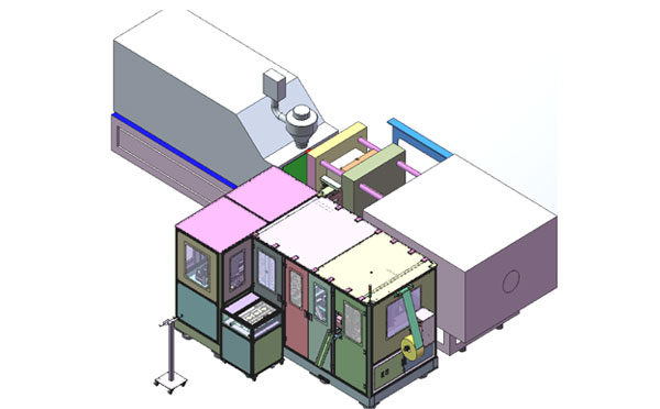
The SWITEK side entry petri dish packing system is a custom made automation system for the stable production of laboratory consumable plastic petri dish with the picking robot, the petri dish assembly, stacking, packing unit etc. integrated as auniformed system for the efficient and stable production of the petri dish. The system can be custome made for a petri dish mold layout design of 2+2, 4+4, 6+6, 8+8 etc.
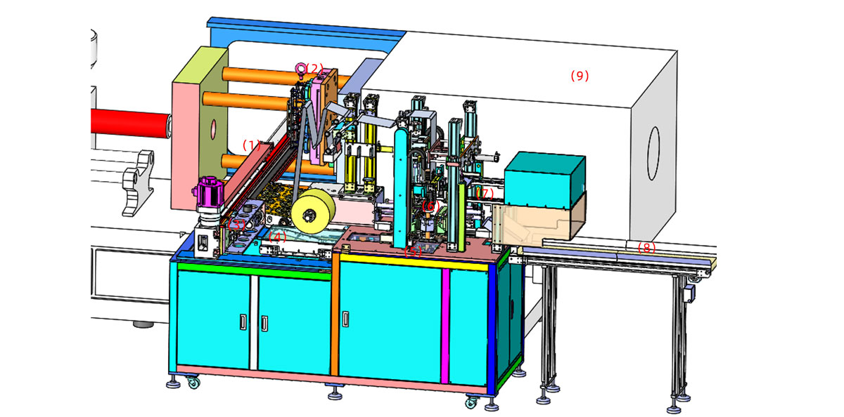
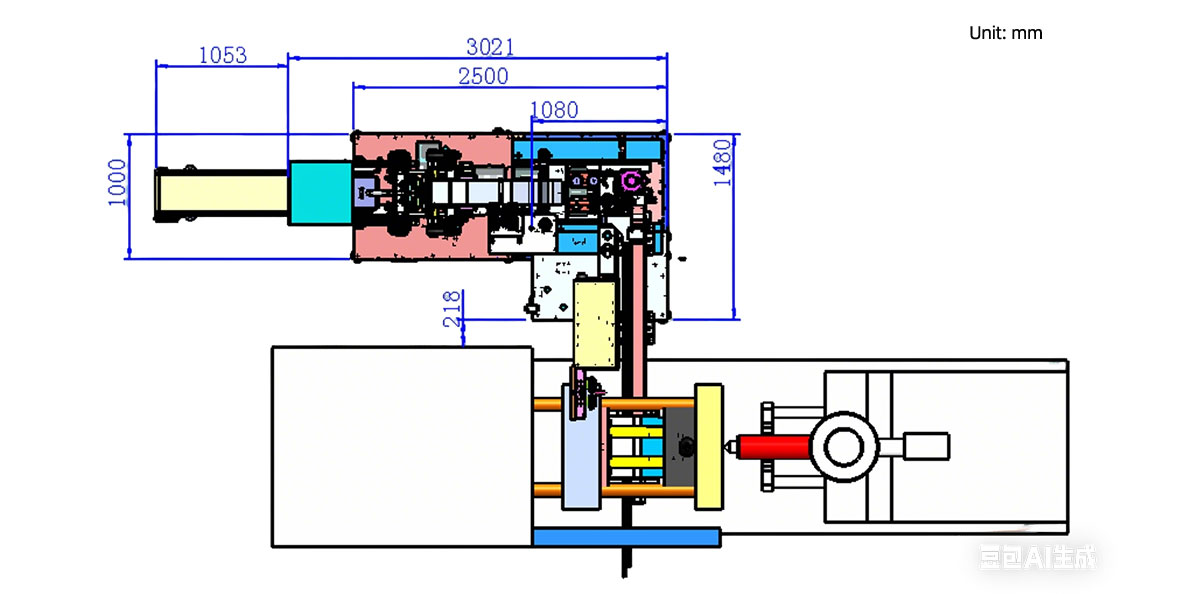
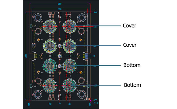
Mold Layout Deisgn
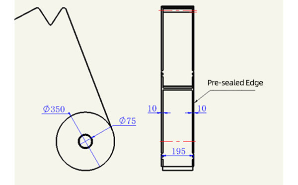
Sleeve Size for Package with Vacuum Request
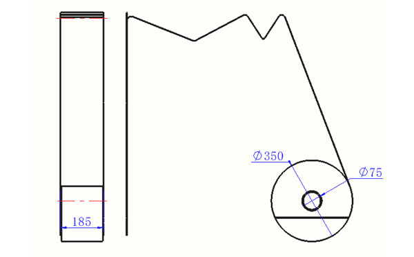
Sleeve Size for Package without Vacuum Request
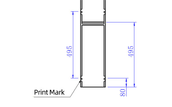
Sleeve (With Mark) Size for Package with Vacuum Request
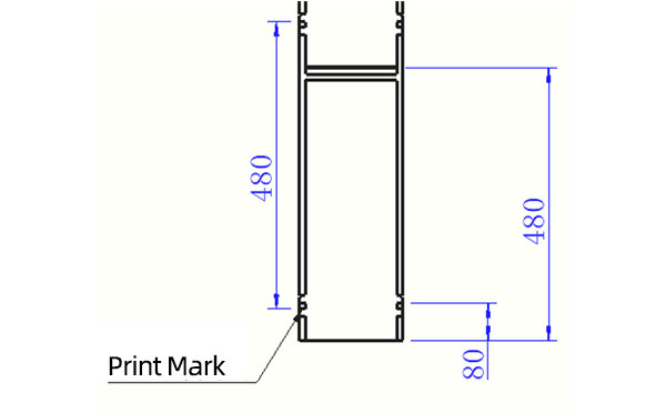
Sleeve (With Mark) Size for Package without Vacuum Request
I think you'll have an overall understanding about the SWITEK top/side entry petri dish packing system. If you still have any other question about it or need any help in your petri dish production project, please feel free to contact SWITEK laboratory consumable plastic parts injection molding solutions team for more information.
HuangYanZheng©Copy Right


